
英语原文共 9 页
中 文 标 题: 船舶自航CFD计算实用指南
2019年 3 月 14 日
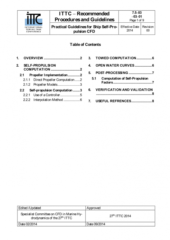
目 录
Practical Guidelines for Ship Self-Propulsion CFD(英文原文)
1. OVERVIEW I
2. SELF-PROPULSION COMPUTATION I
2.1 Propeller Implementation I
2.2 Self-propulsion Computation III
3. TOWED COMPUTATION V
4. OPEN WATER CURVES VI
5. POST-PROCESSING VII
5.1 Computation of Self-Propulsion Factors VII
6. VERIFICATION AND VALIDATION VIII
7. USEFUL REFRENCES VIII
WATERJET APPLICATIONS IN VESSELS THAT OPERATE IN MULTIPLE MODES
(Excerpt).........................................................................................................................................................X
船舶自航CFD计算实用指南
1.概述 1
2.自航计算 1
2.1螺旋桨的数值模拟 1
2.2自航计算 2
3.拖航计算 4
4.敞水特性曲线 4
5.后处理 5
5.1自航因子的计算 5
6.验证和确认 6
7.参考文献 7
WATERJET APPLICATIONS IN VESSELS THAT OPERATE IN MULTIPLE MODES
节选................................................................................................................................................................8
Practical Guidelines for Ship Self-Propulsion CFD
(英文原文)
OVERVIEW
These guidelines are written as a complement to ITTC guidelines 7.5-03-02-03 (2011), “Practical Guidelines for Ship CFD Applications,“ and procedures recommended herein should then be in accordance to those guidelines.
Computation of the self-propulsion factors using CFD essentially mimics the ITTC recommended procedures and guidelines “Testing and extrapolation methods, performance propulsion test,” 7.5-02-03-01.1 (2002). CFD evaluation of self-propulsion factors needs essentially data from three different tests: resistance, self-propulsion and propeller open-water tests. The first two are always performed with CFD, while the last can either be performed with CFD or propeller models based on potential flow theory, for a full numerical evaluation of self-propulsion factors, or can use experimental open water curves if available. In addition, computations can be performed at model scale, full scale, or at model scale with extrapolation to full scale.
SELF-PROPULSION COMPUTATION
Propeller Implementation
-
-
- Direct Propeller Computation
-
The self-propulsion computation requires use of a propeller to provide thrust. The propeller implementation offers several possibilities of different degrees of complexity and computational cost.
In general, direct computation of the propeller provides the highest resolution but also the highest computational cost and the most complexity in terms of grid generation and code capabilities. The CFD code used has to be capable of rotating the propeller grid, which is typically done using sliding or overset grids, or employing the less accurate Multiple Reference Frame (MRF) method. Grid regeneration has also been attempted.
If the propeller will be computed directly, then the grid has to be designed to properly compute the friction forces. The Reynolds number used for the grid design is defined using the 70% radius chord length of the propeller blade and the local speed at that location
Re 0.7RC(0.7R) / (1)
where and are the density and viscosity of the fluid respectively, is the propeller rotational speed, R is the propeller radius and C0.7 is the blade chord length at 70% radius location. Note that the viscosity of water varies with temperature and salinity and so proper values should be used. To evaluate Cf , as needed to compute the wall spacing needed for the desired y as required for direct integration to the wall or use of wall functions, the blade chord length at 70% radius location should also be used. Since the precise propeller rotational speed is not known until a self-propulsion computation is performed, the design of the grid may result in an iterative process to determine the appropriate wall grid spacing. In most cases this can be avoided using an estimate of the propeller rotational speed at self-propulsion.
The time step is selected such that the propeller advances between 0.5 and 2 degrees per time step, with the higher number appropriate for implicit higher-order numerical integration schemes and the lower typical for explicit solvers. This time step, however, may be restricted by the CFL condition or by the implementation of the rotating propeller/moving grid algorithm and may result in a smaller time step than recommended herein.
-
-
- Propeller Models
-
The alternative to direct computation is to model the propeller with some kind coupling be- tween a propeller code and the CFD code. The propeller code receives wake velocities from the CFD code and returns volume forces on the fluid and shaft forces that are taken by the CFD code to accelerate the flow and propel the ship. As expected, increased complexity in the propeller code and the coupling strategy will lead to better results but more cost.
When the propeller is modeled the grid design may need to accommodate specific requ


