2 Heat Exchanger Thermohydraulic
Fundamentals
2.1 HEAT EXCHANGER THERMAL CIRCUIT AND OVERALL CONDUCTANCE EQUATION
In order to develop relationships between the heat transfer rate q, surface area A, fluid terminal temperatures, and flow rates in a heat exchanger, the basic equations used for analysis are the energy conservation and heat transfer rate equations [1]. The energy conservation equation for an exchanger having an arbitrary flow arrangement is
and the heat transfer rate equation is
where
is the true mean temperature difference (MTD), which depends upon the exchanger flow arrangement and the degree of fluid mixing within each fluid stream
is the capacity rate of the cold fluid
is the capacity rate of the hot fluid,
and are cold fluid terminal temperatures (inlet and outlet)
and are hot fluid terminal temperatures (inlet and outlet)
The heat exchanger thermal circuit variables and overall conduction described here are based on Refs. [1, 2].
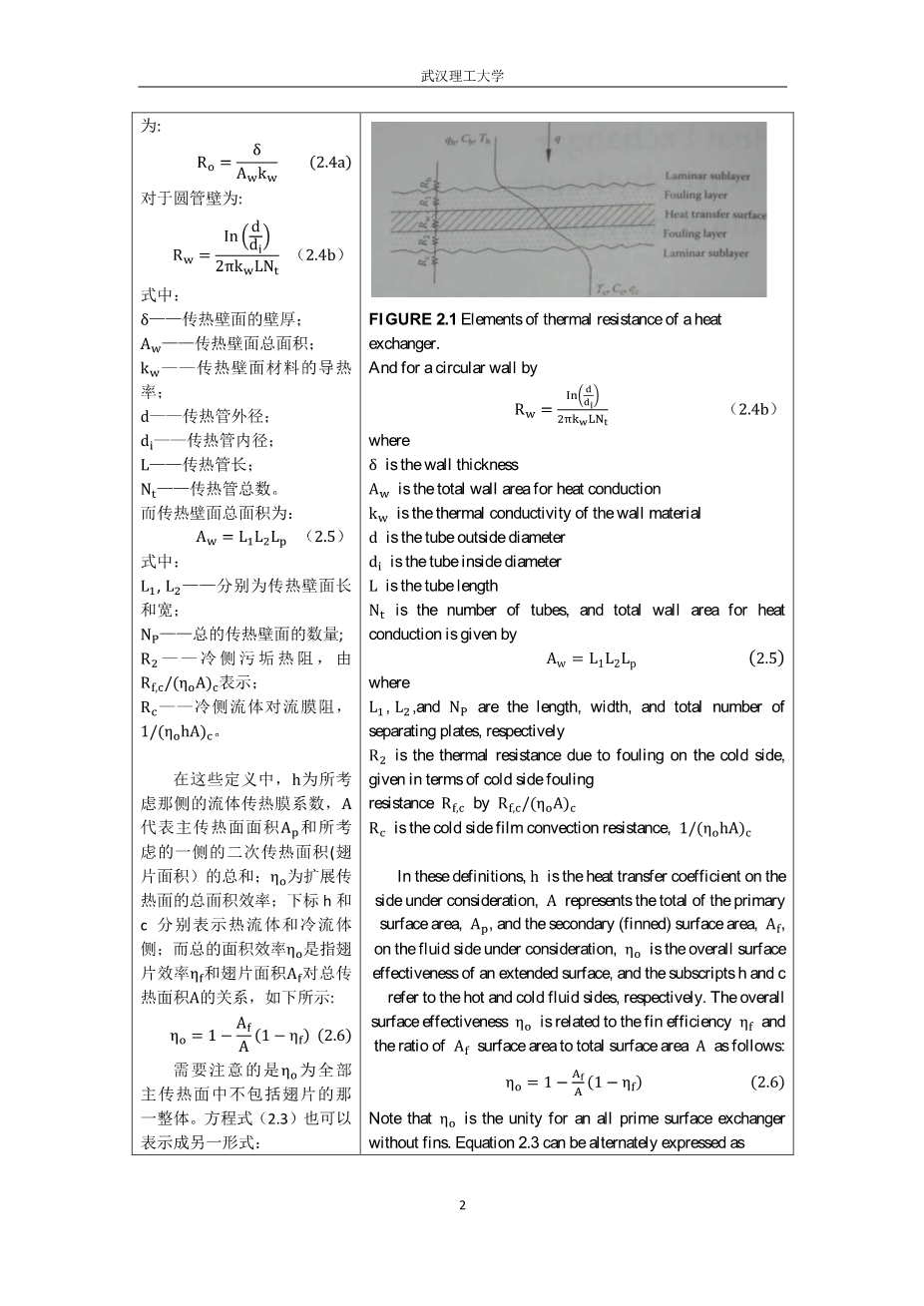
The inverse of the overall thermal conductance UA is referred to as the overall thermal resistance , and it is made up of component resistances in series as shown in Figure 2.1:
where the parameters of the right-hand side of Equation 2.3 are , hot side film convection resistance,; ,thermal resistance due to fouling on the hot side given in terms of fouling resistance (i.ebdquo; values tabulated in standards or textbooks),, ,thermal resistance of the separating wall, expressed for a flat wall by
FIGURE 2.1 Elements of thermal resistance of a heat exchanger.
And for a circular wall by
where
is the wall thickness
is the total wall area for heat conduction
is the thermal conductivity of the wall material
is the tube outside diameter
is the tube inside diameter
is the tube length
is the number of tubes, and total wall area for heat conduction is given by
where
,,and are the length, width, and total number of separating plates, respectively
is the thermal resistance due to fouling on the cold side, given in terms of cold side fouling
resistance by
is the cold side film convection resistance,
In these definitions, is the heat transfer coefficient on the side under consideration, represents the total of the primary surface area, , and the secondary (finned) surface area, , on the fluid side under consideration, is the overall surface effectiveness of an extended surface, and the subscripts h and c refer to the hot and cold fluid sides, respectively. The overall surface effectiveness is related to the fin efficiency and the ratio of surface area to total surface area as follows:
Note that is the unity for an all prime surface exchanger without fins. Equation 2.3 can be alternately expressed as
Since , the overall heat transfer coefficient as per Equation 2.7 may be defined optionally in terms of either hot fluid surface area or cold fluid surface area. Thus, the option of or must be specified in evaluating from the product, . For plain tubular exchangers, based on tube outside surface is given by
The knowledge of wall temperature in a heat exchanger is essential to determine the localized hot spots, freeze points, thermal stresses, local fouling characteristics, or boiling and condensing coefficients. Based on the thermal circuit of Figure 2.1, when is negligible, , is computed from [1,2] as
When , Equation 2.9 further simplifies to
2.2 Heat Exchanger Heat Transfer Analysis Methods
2.2.1 Energy Balance Equation
The first law of thermodynamics must be satisfied in any heat exchanger design procedure at both the macro and microlevels . The overall energy balance for any two-fluid heat exchanger is given by
Equation 2.11 satisfies the “macro” energy balance under the usual idealizations made for the basic design theory of heat exchangers [3].
2.2.2 Heat Transfer
For any flow arrangement, heat transfer for two fluid streams is given by
and the expression for maximum possible heat transfer rate is
The maximum possible heat transfer rate would be obtained in a counterflow heat exchanger with very large surface area and zero longitudinal wall heat conduction, and the actual operating conditions are the same as the theoretical conditions.
2.2.3 Basic Methods To Calculate Thermal Effectiveness
There are four design methods to calculate the thermal effectiveness of heat exchangers:
- method
- method
- method
- method
The basics of these methods are discussed next. For more details on these methods, refer to Refs. [1,2].
2.2.3.1 Method
The formal introduction of the method for the heat exchanger analysis was in 1942 by London and Seban [4]. In this method, the total heat transfer rate from the hot fluid to the cold fluid in the exchanger is expressed as
Where is the heat exchanger effectiveness. It is nondimensional and for a direct transfer type heat exchanger, in general, it is dependent on , ,and the flow arrangement:
These three nondimensional parameters, , , and , are defined next.
Heat capacity rate ratio, : this is simply the ratio of the smaller to larger heat capacity rate for the two fluid streams so that .
where
refers to the product of mass and specific heat of the fluid
the subscripts min and max refer to the and sides, respectively
In a two-fluid heat exchanger, one of the streams will usually undergo a greater temperature change than the other. the first stream is said to
剩余内容已隐藏,支付完成后下载完整资料


英语原文共 24 页,剩余内容已隐藏,支付完成后下载完整资料
资料编号:[146150],资料为PDF文档或Word文档,PDF文档可免费转换为Word
以上是毕业论文外文翻译,课题毕业论文、任务书、文献综述、开题报告、程序设计、图纸设计等资料可联系客服协助查找。


