|
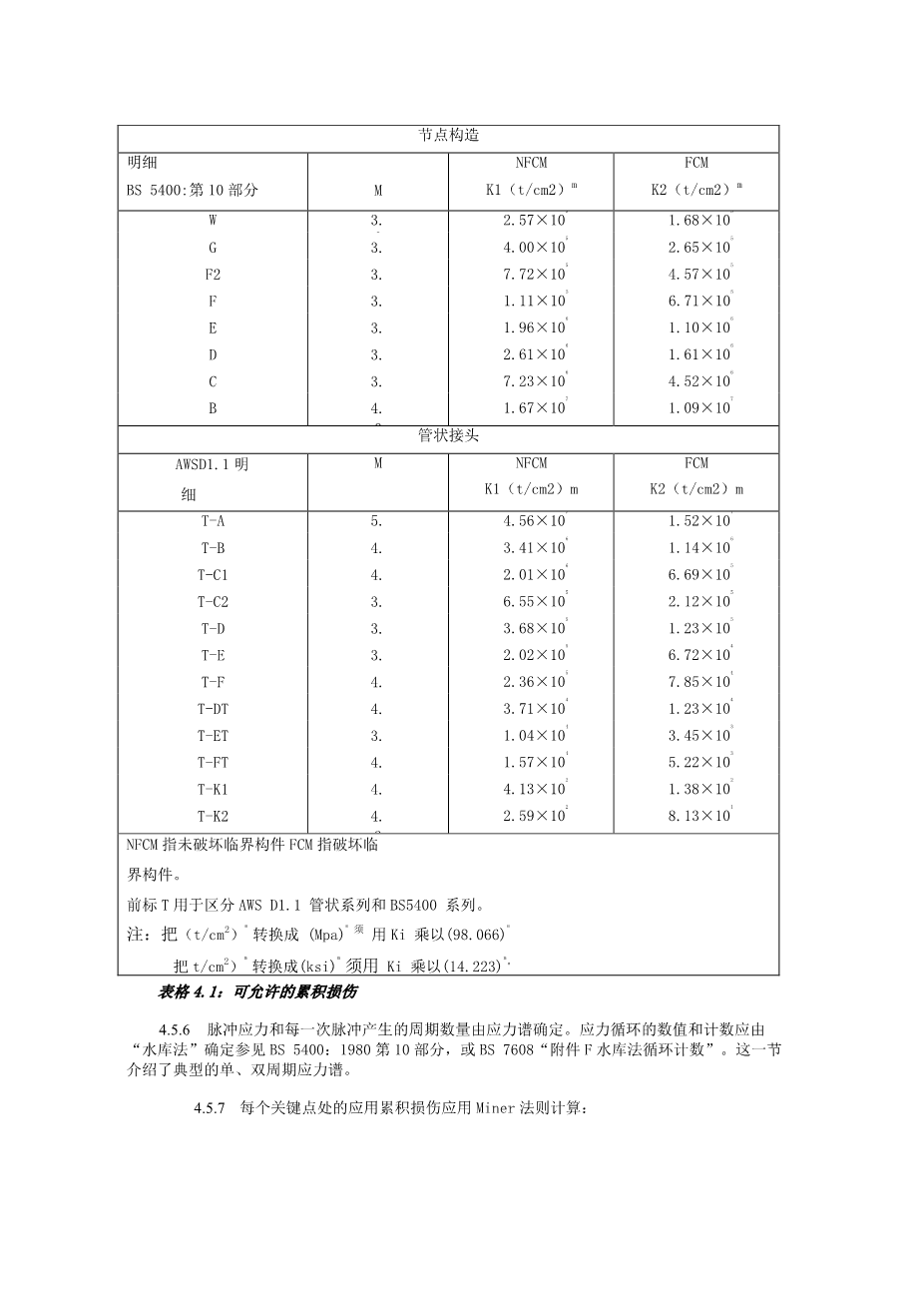
JOINT DETAILS |
|||
|
Detail Class |
NFCM |
FCM |
|
|
BS 5400: Part 10 |
M |
K1 (t/cm2 ) m |
K2 (t/cm2 ) m |
|
W |
3.0 |
2.57x10s |
1.68x10⁵ |
|
G |
3.0 |
4.00x10⁵ |
2.65 x10⁵ |
|
F2 |
3.0 |
7.72x10⁵ |
4.57x10⁵ |
|
F |
3.0 |
1.11x10⁵ |
6.71x10⁵ |
|
E |
3.0 |
1.96x10⁶ |
1.10x10⁶ |
|
D |
3.0 |
2.61x10⁶ |
1.61x10⁶ |
|
C |
3.5 |
7.23x10⁶ |
4.52x10⁶ |
|
B |
4.0 |
1.67x10⁷ |
1.09x10⁷ |
|
TUBULAR JOINTS |
|||
|
Detail Class |
M |
NFCM |
FCM |
|
AWSD1.1 |
K1 (t/cm2 ) m |
K2 (t/cm2 ) m |
|
|
T-A |
5.8 |
4.56x10⁷ |
1.52x10⁷ |
|
T-B |
4.4 |
3.41x10⁶ |
1.14x10⁶ |
|
T-C1 |
4.1 |
2.01x10⁶ |
6.69x10⁵ |
|
T-C2 |
3.6 |
6.55x10⁵ |
2.12x10⁵ |
|
T-D |
3.3 |
3.68x10⁵ |
1.23 x10⁵ |
|
T-E |
3.2 |
2.02x10⁵ |
6.72x10⁴ |
|
T-F |
4.6 |
2.36x10⁵ |
7.85x10⁴ |
|
T-DT |
4.4 |
3.71x10⁴ |
1.23 x10⁴ |
|
T-ET |
3.4 |
1.04x10⁴ |
3.45x10³ |
|
T-FT |
4.2 |
1.57x10⁴ |
5.22x10³ |
|
T-K1 |
4.5 |
4.13x10² |
1.38x10² |
|
T-K2 |
4.3 |
2.59x10² |
8.13X101 |
|
NFCM is Non-Fracture Critical Members |
|||
|
FCM is Fracture Critical Members |
|||
|
T preface is used to distinguish AWS D1.1 tubular class from BS5400 class. |
|||
|
Note: To convert (t/cm2) m |
to (Mpa)m multiply Ki by(98.066)m |
||
|
To convert (t/cm2) m to (ksi)m multiply Ki by(14.223)m |
|||
Table 4.1: Allowable Cumulative Damage
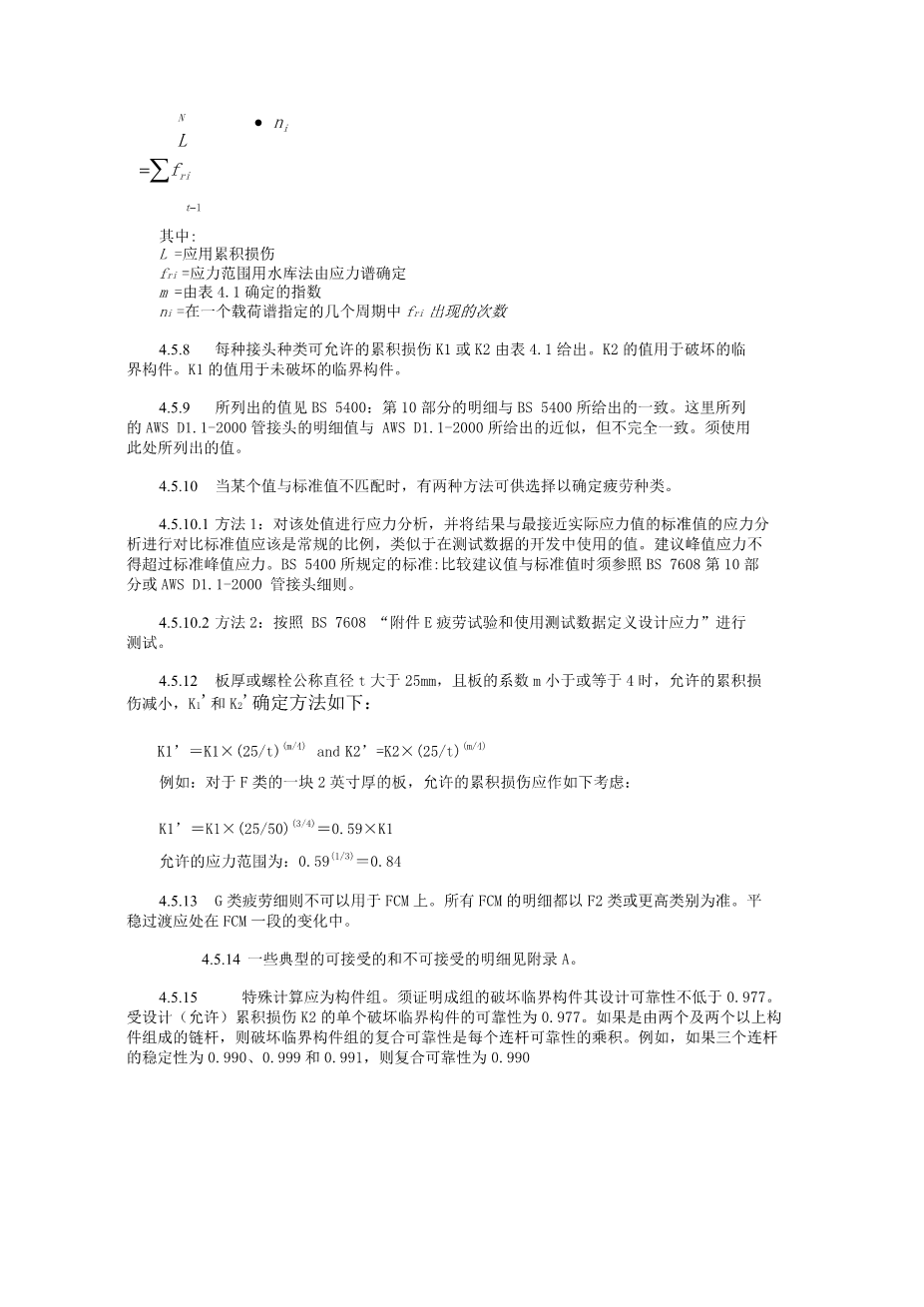
- Fluctuating stresses and the number of cycles of each fluctuation shall be determined from the stress spectra. Stress cycle value and counting shall be done by the “reservoir method.” See BS 5400: Part 10, 1980 or BS 7608 “Annex F Cycle counting by the reservoir method”. Typical single and double cycle stress spectra are shown in this section.
- The applied cumulative damage at each critical point shall be calculated using Miners rule:
SSA/ZPMC Specification for 2 Cranes
60/125
June 8, 2006
TECHNICAL SPECIFICATIONS
FOR TWO (2) POST PANAMAX CONTAINER GANTRY CRANE
FOR
STEVEDORING SERVICES OF AMERICA
N
l=z frm bull; ^
t-i
where:
L = applied cumulative damage
fri = ith stress range determined from the stress spectra using the reservoir method m = exponent from Table 4.1
ni = number of occurrences offri during the specified number of cycles for each load spectrum
- The allowable cumulative damage for each joint classification K1 or K2 is given in Table 4.1. K2 values shall be used for fracture critical members. K1 values shall be used for non-fracture critical members.
- The values tabulated for BS 5400: Part 10 details are identical to those given in BS 5400. The values tabulated here for AWS D1.1-2000 tubular details are close, but not identical, to those given in AWS D1.1-2000. The tabulated values given here shall be used.
- When a detail does not match a standard detail, two alternative methods may be used to determine the fatigue class:
- Alternate 1: Prepare a stress analysis of the detail and compare the results to a stress analysis of a typical standard detail which is most similar to the actual detail. The standard detail shall be of usual proportions, similar to the detail used in the development of the test data. The peak stress in the proposed detail shall not exceed peak stress in the standard detail. Criteria in BS 5400: Part 10, BS 7608, or the AWS D1.1-2000 tubular details shall be used for comparing proposed detail to the standard detail.
- Alternate 2: Conduct tests in accordance with BS 7608 “Annex E Fatigue testing and the use to test data to define design stresses.”
-
For a plate thickness or nominal bolt diameter, t, greater than 25 mm and, for plates, where the coefficient m is less than or equal to four, a reduced allowable cumulative
剩余内容已隐藏,支付完成后下载完整资料


英语原文共 13 页,剩余内容已隐藏,支付完成后下载完整资料
资料编号:[138760],资料为PDF文档或Word文档,PDF文档可免费转换为Word


