
英语原文共 13 页,剩余内容已隐藏,支付完成后下载完整资料
|
SECTION 5 MACHINERY PIPING SYSTEMS
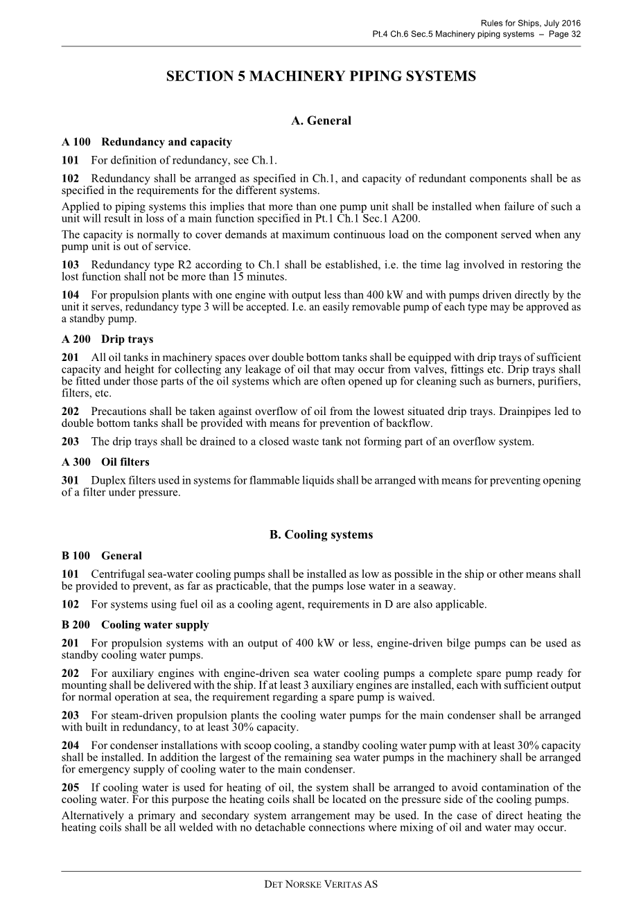
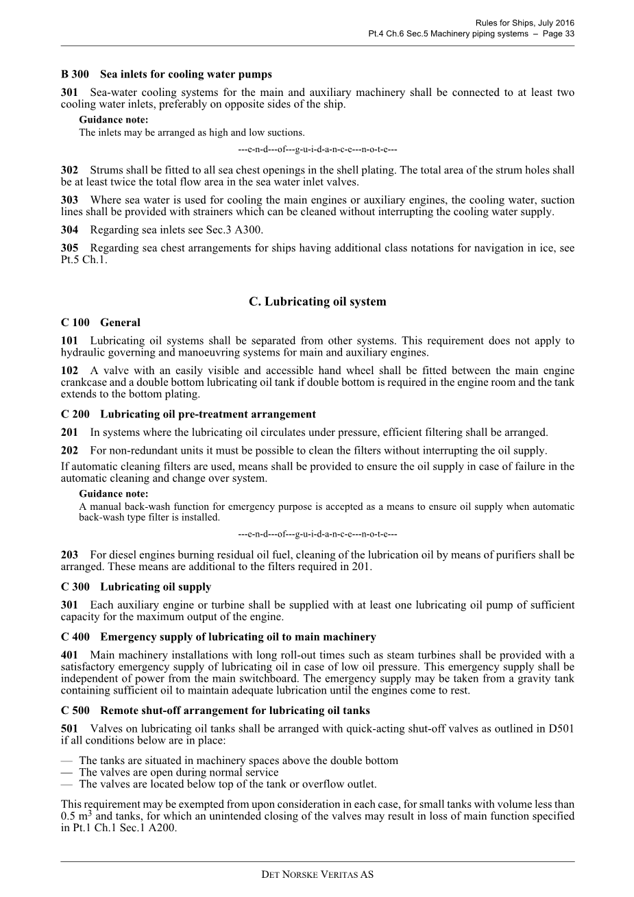
A 100 Redundancy and capacity 101 For definition of redundancy, see Ch.1. 102 Redundancy shall be arranged as specified in Ch.1, and capacity of redundant components shall be as specified in the requirements for the different systems. Applied to piping systems this implies that more than one pump unit shall be installed when failure of such a unit will result in loss of a main function specified in Pt.1 Ch.1 Sec.1 A200. The capacity is normally to cover demands at maximum continuous load on the component served when any pump unit is out of service. 103 Redundancy type R2 according to Ch.1 shall be established, i.e. the time lag involved in restoring the lost function shall not be more than 15 minutes. 104 For propulsion plants with one engine with output less than 400 kW and with pumps driven directly by the unit it serves, redundancy type 3 will be accepted. I.e. an easily removable pump of each type may be approved as a standby pump. A 200 Drip trays 201 All oil tanks in machinery spaces over double bottom tanks shall be equipped with drip trays of sufficient capacity and height for collecting any leakage of oil that may occur from valves, fittings etc. Drip trays shall be fitted under those parts of the oil systems which are often opened up for cleaning such as burners, purifiers,filters, etc. 202 Precautions shall be taken against overflow of oil from the lowest situated drip trays. Drainpipes led to double bottom tanks shall be provided with means for prevention of backflow. 203 The drip trays shall be drained to a closed waste tank not forming part of an overflow system. A 300 Oil filters 301 Duplex filters used in systems for flammable liquids shall be arranged with means for preventing opening of a filter under pressure. B. Cooling systems B 100 General 101 Centrifugal sea-water cooling pumps shall be installed as low as possible in the ship or other means shall be provided to prevent, as far as practicable, that the pumps lose water in a seaway. 102 For systems using fuel oil as a cooling agent, requirements in D are also applicable. B 200 Cooling water supply 201 For propulsion systems with an output of 400 kW or less, engine-driven bilge pumps can be used as standby cooling water pumps. 202 For auxiliary engines with engine-driven sea water cooling pumps a complete spare pump ready for mounting shall be delivered with the ship. If at least 3 auxiliary engines are installed, each with sufficient output for normal operation at sea, the requirement regarding a spare pump is waived. 203 For steam-driven propulsion plants the cooling water pumps for the main condenser shall be arranged with built in redundancy, to at least 30% capacity. 204 For condenser installations with scoop cooling, a standby cooling water pump with at least 30% capacity shall be installed. In addition the largest of the remaining sea water pumps in the machinery shall be arranged for emergency supply of cooling water to the main condenser. 205 If cooling water is used for heating of oil, the system shall be arranged to avoid contamination of the cooling water. For this purpose the heating coils shall be located on the pressure side of the cooling pumps. Alternatively a primary and secondary system arrangement may be used. In the case of direct heating the heating coils shall be all welded with no detachable connections where mixing of oil and water may occur. B 300 Sea inlets for cooling water pumps 301 Sea-water cooling systems for the main and auxiliary machinery shall be connected to at least two cooling water inlets, preferably on opposite sides of the ship. Guidance note: The inlets may be arranged as high and low suctions 302 Strums shall be fitted to all sea chest openings in the shell plating. The total area of the strum holes shall be at least twice the total flow area in the sea water inlet valves. 303 Where sea water is used for cooling the main engines or auxiliary engines, the cooling water, suction lines shall be provided with strainers which can be cleaned without interrupting the cooling water supply. 304 Regarding sea inlets see Sec.3 A300. 305 Regarding sea chest arrangements for ships having additional class notations for navigation in ice, see Pt.5 Ch.1. C. Lubricating oil system C 100 General 101 Lubricating oil systems shall be separated from other systems. This requirement does not apply to hydraulic governing and manoeuvring systems for main and auxiliary engines. 102 A valve with an easily visible and accessible hand wheel shall be fitted between the main engine crankcase and a double bottom lubricating oil tank if double bottom is required in the engine room and the tank extends to the bottom plating. C 200 Lubricating oil pre-treatment arrangement 201 In systems where the lubricating oil circulates under pressure, efficient filtering shall be arranged. 202 For non-redundant units it must be possible to clean the filters without interrupting the oil supply. If automatic cleaning filters are used, means shall be provided to ensure the oil supply in case 全文共56840字,剩余内容已隐藏,支付完成后下载完整资料 资料编号:[13276],资料为PDF文档或Word文档,PDF文档可免费转换为Word |
以上是毕业论文外文翻译,课题毕业论文、任务书、文献综述、开题报告、程序设计、图纸设计等资料可联系客服协助查找。


