
英语原文共 4 页,剩余内容已隐藏,支付完成后下载完整资料
Study on the Acoustic Performance of Perforated Duct Muffler
Abstract
In engine exhaust systems, perforated element is usually used to improve the acoustic attenuation performance of mufflers. To predict the acoustic attenuation performance of perforated duct mufflers under working conditions, three-dimensional finite element method considering the effect of gas flow was developed. In the numerical computations, perforation acoustic impedance model was applied to consider the acoustic influencer of perforated element with gas flow. To verify the accuracy of predictions, a test bench was build up to measure the transmission loss of perforated duct mufflers with gas flow. The predictions and measurement showed that the effect of porosity and Mach number of gas flow is obvious on the transmission loss of perforated duct mufflers.
Key Words:muffler;exhaust system;finite element analysis;Mach number;pipe flowSECTION I. Introduction
With good acoustic attenuation performance and flow resistance performance, perforated duct muffler is effective for the noise control and used in engine exhaust systems widely. The acoustic performance of perforated duct mufflers is always obtained by experiment measuring and theoretical predicting [1]. Many researches have been done for the acoustic predictions of perforated duct mufflers without flow [1][2][3]. However, the effect of gas flow should be considered in the acoustic predictions because gas flow always exists inside the mufflers under working conditions.
Since the perforated elements are complicated, the perforated acoustic impedance is usually used to simulate the acoustic influence of perforated elements on the acoustic attenuation performance predictions. The transmission loss of perforated duct muffler without and with mean flow was first calculated by Sullivan [4][5] with one-dimensional analytical approach. But, the results could not be obtained correctly in high frequency range because of the frequency limitation of one-dimensional analytical approach [1]. Three-dimensional boundary element method was then applied by Wang [6] to predict the transmission loss of perforated duct mufflers, and the accuracy problem for results in high frequency range was solved because the multi-dimensional waves can be considered by three-dimensional method. The perforation impedance with grazing flow used above was obtained by Sullivan [5], however, the effect of grazing flow on the reactance of perforation impedance was ignored in Sullivan#39;s expression. Recently, Lee and Ih [7] gave a perforation impedance model with lots of experimental results, then the transmission loss of perforated duct mufflers was predicted with the perforation impedance model. Unfortunately, the calculation method used by Lee and Ih [7] was still one-dimensional analytical approach.
In present paper, three-dimensional finite element method was developed to compute the acoustic attenuation performance of straight-through perforated duct mufflers with gas flow. In the numerical computations, a new perforation acoustic impedance model was applied to consider the acoustic influence of perforated elements. The predictions agreed the measurement well, which verifies the accuracy of the new perforated impedance model.
SECTION II. Numerical Computation
A. Finite element numerical computation
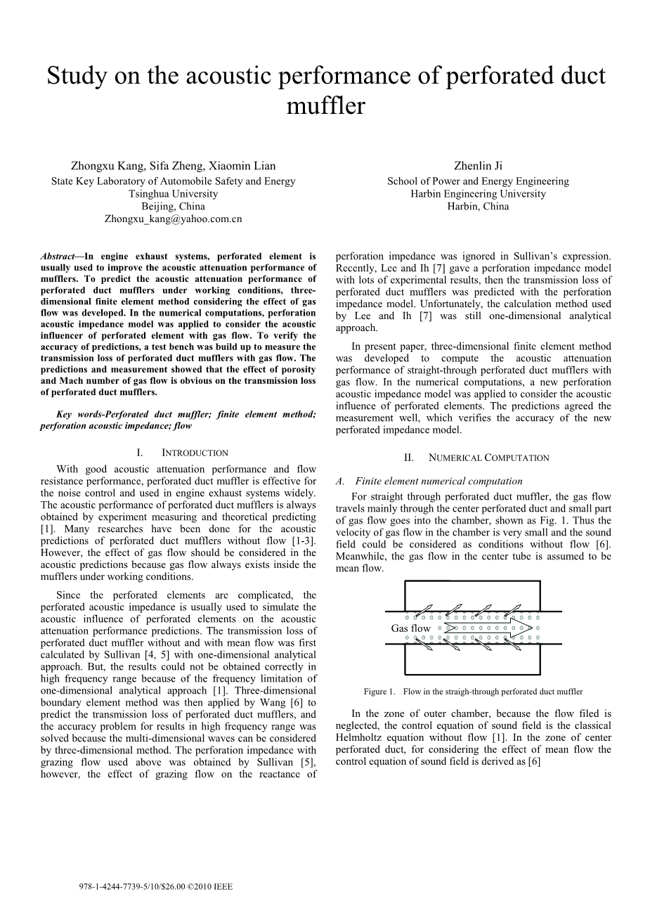
For straight through perforated duct muffler, the gas flow travels mainly through the center perforated duct and small part of gas flow goes into the chamber, shown as Fig. 1. Thus the velocity of gas flow in the chamber is very small and the sound field could be considered as conditions without flow [6]. Meanwhile, the gas flow in the center tube is assumed to be mean flow.
Figure 1 Flow in the straigh-through perforated duct muffler
In the zone of outer chamber, because the flow filed is neglected, the control equation of sound field is the classical Helmholtz equation without flow [1]. In the zone of center perforated duct, for considering the effect of mean flow the control equation of sound field is derived as [6]
where, ϕ is acoustic velocity potential, k0=omega;/c0 is wave number, omega; is angle frequency, c0 is sound velocity, M=V/c0 is Mach number of mean flow, V is mean flow velocity, z is the flow direction, j is imaginary unit. The relation between the acoustic velocity potential and sound pressure p, particle velocity u is
in witch, rho;0 is the medium density.
The boundary conditions of perforated duct muffler models contain: (1) rigid wall boundary at the walls, part;ϕ/part;n=0, (2) particle velocity boundary at inlet, part;ϕ/part;n=minus;1,
(3) acoustic anechoic boundary at outlet, z=p/un=rho;0c0,(4) perforation acoustic impedance between two sides of perforated duct wall, zp=Delta;p/un,zp is the perforation impedance, Delta;p is t
全文共19375字,剩余内容已隐藏,支付完成后下载完整资料
资料编号:[17277],资料为PDF文档或Word文档,PDF文档可免费转换为Word


